Building my own network controlled LED dimmer

Moderator: leecollings

User avatar
Quindor
Posts: 31
Joined: Sunday 06 April 2014 23:05
Target OS: Raspberry Pi / ODroid
Domoticz version:
Contact:

Building my own network controlled LED dimmer

Post by Quindor »

I've been using Domoticz for a while now and it's been excellent with KAKU and Elro on/off modules.

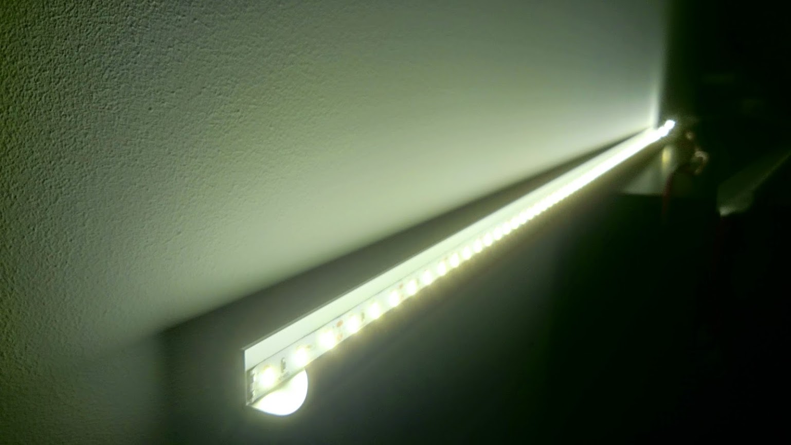
But, for the new house I'm building I wish to use some more unique and controllable LED lighting. That means I need a system which I can remotely control to dim to whatever value I send to it.

I hope I selected the right forum, so here goes:

My goal is basically to create a system which senses current light in a certain room, and then senses movement. If movement is detected the LED's should gradually fade up to a level. But this level depends on the time of day, during the night I wish them to light to 20% for instance and during the day or evening I wish this to be 80%. The same thing goes for color (most lights will be warm white though). I wish to be able to control color and intensity based on presence detection, time of day, etc.

I also wish to build it into my cellar and simulate daylight with it. Combining a Warm White and Cool White strip with maybe an RGB strip to simulate natural light and the morning, midday and afternoon cycle with it a little bit. Make it feel more natural if I happen to walk into the cellar, again all brightness dependent and motion controlled.

I call it "Time dependent variable LED lighting" or something. :P

To try and accomplish this I have tested several existing commercial products, but they all don't completely suite my needs.
AppLamp: Nice, but their RGBW dimmers aren't RGBW, they are RGB or W. Also they are not able to gradually fade between set values. Their price, if you buy Mi.Light in China is fair
Fibaro RGBW: Nice module and actually RGBW. It even has a setting to do the fading and everything. But Z-wave is not always reliable (for me) and it's price is way up there!

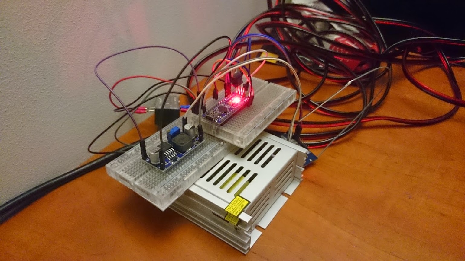
So I have created my own prototype with a Arduino Nano combined with some mosfets coupled to a RM-04. The Arduino has PWM pins which can dim the LED strips using the mosfets from a value of 0 (off) to 255 (full brightness). It does so at about 866Hz so no visual flicking is visible to the human eye.

The RM-04 WiFi is a WiFi-to-Serial bridge. Basically it connects to your WiFi automatically/itself and then opens a TCP port which it links to some onboard serial pins. Couple these serial pins with your Arduino and you have a way to remotely talk to your Arduino.

The cost of building QLEDdimmer v0.85 (my prototype) would be about 20$ for all components combined if I build them in an order of 10 or so. The WiFi module is the most expensive of that and recently a new module surfaced which does not cost 10$ but 5$ so that would make it even cheaper!

I've made a program that runs on the Arduino Nano which listens and accepts serial input in a 4 number format (I wish to control 4 Mosfets/LED strips at most at the same time from one module). The program uses a library which automatically fades between the values sent. I have set the program to always take 5 seconds to fade between current and new value.

So, from a Linux system I can now perform the following:

echo 100100100100 | nc 10.10.128.113 8080 (Fades all channels from 000 to 100 in 5 seconds)

echo 255255255255 | nc 10.10.128.113 8080 (Fades all channels from 100 to 255 in 5 seconds)

echo 000000000000 | nc 10.10.128.113 8080 (Fades everything back from current value (255 if following last example) to 000 in 5 seconds)

And so far, this all works now. This is still a raw prototype, for instance, if you don't give a value for a certain channel, it will revert back to 000, making it hard to control all the channels separately. But let's say that will become a feature for v2. ;)

For now, I'm looking for a way for Domoticz to control the whole. I have got it working using Lua scripts to turn it on and off to a set value. But I would much rather integrate it as a dimmer type of switch. From what I've been able to gather there is no Lua functionality to, for instance, say that dimmer 0% - 100% corresponds to 000 - 255 and then to send that value to all channels connected to that particular module. That is all of the functionality I would want to create for v1 of my project.

I understand in the end it would be best of my Arduino program would understand json input strings and probably a lot of other ways to better create what I've built, but I'm not really a programmer. :(

Does anyone have a great idea on how to integrate this into Domoticz?
Last edited by Quindor on Wednesday 24 September 2014 1:56, edited 1 time in total.
http://www.campzone.nl World's Largest Outdoor LANParty, 1750+ people gather for 11 days! 10Gbit routed network, 1Gbit full-duplex internet, etc.
User avatar
Quindor
Posts: 31
Joined: Sunday 06 April 2014 23:05
Target OS: Raspberry Pi / ODroid
Domoticz version:
Contact:

Re: Building my own network controlled LED dimmer

Post by Quindor »

This is the code I'm currently using a works.

Yes, it's a bit rough. ;) As I mentioned, I'm no programmer.

Code: Select all

/*
PWM Networked LEDFader v0.9
Watches for 12 character serial communication - first 3 characters are PWM signal for pin 12, second set of 3 for pin 11, third for pin 10 and last set for pin 09. Values of 000-255 are accepted
Set to run with Chinese Arduino Nano v3
*/

#include <math.h>
#include <LEDFader.h>
    int PWR1, PWR2, PWR3, PWR4, x1, x2, x3, x4, x5, x6, x7, x8, x9, x10, x11, x12;
    int hundreds, tens, ones;
    int Dtens, Dones;
    char *h, *t, *o, *Dt, *Do;
    LEDFader led1 = LEDFader(12);
    LEDFader led2 = LEDFader(11);
    LEDFader led3 = LEDFader(10);
    LEDFader led4 = LEDFader(9);

	
void setup() {
  led1.fade(15, 6000);  
  led2.fade(15, 6000);  
  led3.fade(15, 6000);  
  led4.fade(15, 6000);  
// Initialize the digital PWM pins as outputs.
  pinMode(12,  OUTPUT);    // Set pin as output
  pinMode(11,  OUTPUT);    // Set pin as output
  pinMode(10,  OUTPUT);    // Set pin as output
  pinMode(9,  OUTPUT);    // Set pin as output
  Serial.begin(115200);   
}


//******************************************************************************
// The main loop just watches for 12 characters string from Serial
// It also keeps the LED fade alive if running
//******************************************************************************
void loop() {
   led1.update();
   led2.update();
   led3.update();
   led4.update();   
  if (Serial.available()>=12)   {    
      readloop();  
      }
   delay(10);
//   Serial.flush();
   }
   
   
//******************************************************************************
// This loop reads reads and processes the values it receives through Serial
//******************************************************************************
void readloop() {
   hundreds = Serial.read();   
   *h = hundreds;              
   x1 = atoi(h); 
   tens = Serial.read();
   *t = tens;
   x2 = atoi(t); 
   ones = Serial.read();
   *o = ones;
   x3 = atoi(o);
   hundreds = Serial.read();   
   *h = hundreds;              
   x4 = atoi(h); 
   Dtens = Serial.read();
   *Dt = Dtens;
   x5 = atoi(Dt);
   Dones = Serial.read();
   *Do = Dones;  
   x6 = atoi(Do);
   hundreds = Serial.read();   
   *h = hundreds;              
   x7 = atoi(h); 
   Dtens = Serial.read();
   *Dt = Dtens;
   x8 = atoi(Dt);
   Dones = Serial.read();
   *Do = Dones;  
   x9 = atoi(Do); 
   hundreds = Serial.read();   
   *h = hundreds;              
   x10 = atoi(h); 
   Dtens = Serial.read();
   *Dt = Dtens;
   x11 = atoi(Dt);
   Dones = Serial.read();
   *Do = Dones;  
   x12 = atoi(Do);
   Serial.read();    // Clears what is left in buffer such as NewLine

   PWR1 = 100*x1 + 10*x2 + x3;     // Compiling the PWM signal
   PWR2 = 100*x4 + 10*x5 + x6;
   PWR3 = 100*x7 + 10*x8 + x9;
   PWR4 = 100*x10 + 10*x11 + x12;

   
// Enage LEDfader library to fade LEDs to the desired PWM value. It will automatically determine the amount of steps to take within the given amount of ms.
   led1.fade(PWR1, 6000);
   led2.fade(PWR2, 6000);
   led3.fade(PWR3, 6000);
   led4.fade(PWR4, 6000);
// Output values it has received
    Serial.println("Value is: ");
    Serial.println(PWR1);
    Serial.println(PWR2);
    Serial.println(PWR3);
    Serial.println(PWR4);
// Flush the serial buffer to accept new input
   Serial.flush();
}  
Last edited by Quindor on Wednesday 24 September 2014 1:45, edited 1 time in total.
http://www.campzone.nl World's Largest Outdoor LANParty, 1750+ people gather for 11 days! 10Gbit routed network, 1Gbit full-duplex internet, etc.
User avatar
Quindor
Posts: 31
Joined: Sunday 06 April 2014 23:05
Target OS: Raspberry Pi / ODroid
Domoticz version:
Contact:

Re: Building my own network controlled LED dimmer

Post by Quindor »

Some photo's:

Image
The prototype setup with the mentioned Arduino Nano v3, a 12v power supply with a regulator to regulate it down to 5v for the WiFi module. And the mosfet connected to the LED strip

Image
The WiFi module

Image
The LED strip in an Aluminium strip from the "bouwmarkt"
http://www.campzone.nl World's Largest Outdoor LANParty, 1750+ people gather for 11 days! 10Gbit routed network, 1Gbit full-duplex internet, etc.
User avatar
Quindor
Posts: 31
Joined: Sunday 06 April 2014 23:05
Target OS: Raspberry Pi / ODroid
Domoticz version:
Contact:

Re: Building my own network controlled LED dimmer

Post by Quindor »

No one who can provide a bit of insight on how to achieve this?
http://www.campzone.nl World's Largest Outdoor LANParty, 1750+ people gather for 11 days! 10Gbit routed network, 1Gbit full-duplex internet, etc.
ThinkPad
Posts: 890
Joined: Tuesday 30 September 2014 8:49
Target OS: Linux
Domoticz version: beta
Location: The Netherlands
Contact:

Re: Building my own network controlled LED dimmer

Post by ThinkPad »

I fiddled around with this example: http://blog.thiseldo.co.uk/?p=281 for a while. I used it on my Arduino with 3x TIP120 FET's connected, so i could drive a LED-strip.
Worked quite well. Only downside is that it requires a network cable to the Arduino. Your wireless solution is better in that way.

Maybe one day i will pick it up again, and see if i can integrate it in Domoticz. However a 433Mhz wireless RGB controller is only $20 or so from DX.com, so i would probably go that way if i want to control my RGB strips. The DX.com controller is fully supported by RFXcom also, which makes it easier to integrate into Domoticz than hacking together some scripts myself.
I am not active on this forum anymore.
Chopper_Rob
Posts: 17
Joined: Wednesday 28 May 2014 21:11
Target OS: Raspberry Pi / ODroid
Domoticz version:
Location: NL
Contact:

Re: Building my own network controlled LED dimmer

Post by Chopper_Rob »

After a quick search i found a way to read a dimmer value, although it seems it only goes from 0 - 15, where 15 is 100%. (so only 16 steps)
But you can use this to convert it to a 0-255 range.

value = otherdevices_svalues['dimmer_name']
print (value*255/15)

It's not ideal to only have 16 steps, but maybe you can use it to test your setup.
User avatar
Quindor
Posts: 31
Joined: Sunday 06 April 2014 23:05
Target OS: Raspberry Pi / ODroid
Domoticz version:
Contact:

Re: Building my own network controlled LED dimmer

Post by Quindor »

Actually, I finished my script a few weeks ago and have been tuning and perfecting it for a little bit since. Seems to be functioning quite well now.

Code: Select all

commandArray = {}
if devicechanged['TestDimmer'] then
        NewValue = (otherdevices_svalues['TestDimmer']) * 8;
                if NewValue <100 then DimNumber=("0"..(NewValue).."");
                end
                if NewValue <10 then DimNumber=("00"..(NewValue).."");
                end
                if NewValue >100 then DimNumber=NewValue ;
                end
        PWMOutput = (""..(DimNumber)..(DimNumber)..(DimNumber)..(DimNumber).."");
        print ("Dimming TestDimmer to " .. (DimNumber) .. " ");
        print ("Settings PWM Output to " .. (PWMOutput) .. " ");
        runcommand = "echo " .. PWMOutput .. " | nc 10.10.128.113 8080";
        print (runcommand)
                os.execute(runcommand)
                os.execute(runcommand)
        end
return commandArray

*Disclaimer, I'm not a code writer and this can probably be done a lot simpler and more efficient, but I got it to work this way. ;)
** For some very odd reason I have to execute the OS command twice to get it to always do what I ask of it. This is a bug somewhere in my code.

It uses the 16 dimmer values you mentioned and converts those to a value in the 0...255 range, makes it 4 in a row(my LED dimmer will support 4 separate channels in the end) and then uses netcat (a linux utility) to send the line of numbers to my LED dimmer. Works perfectly! The Arduino code makes it fade between whatever the current value is and the new value take 6 seconds (And automatically calculates the steps) so fading is always nice and gradual. Quickly changing the value keeps the fade going and seems to work well too.

Just 2 problems remain. Or rather, one missing feature and on bug I think.

Missing feature: You cannot set a dimmer value of 0% in a scene (6% is the lowest)
Bug: Turning off the device in a scene sets it to value 255, turning it off manually sets it to 000 as it should

The reason I'm building this is the same as @Thinkpad mentioned above. Costs. All in all, the cost of 1 module will be around 25$ to 30$ when finished I think. It will be able to drive multiple LED strips with that and suit my purposes to become the main (Warm white) lighting system for in my house. Of course something like this (not exactly though) is available commercially but those cost ~100$ per module (Such as the Fibaro modules). A lot more time is involved in building them though, but that is also part of the fun.

I'm hoping to finalize my PCB board design this week and do a test batch to see if that is going to work!

If that works, v1 is complete. v2 is making the channels work separately (enabling the usage of color LED's for instance, etc.). But that is for a later time!
Last edited by Quindor on Sunday 02 November 2014 22:59, edited 1 time in total.
http://www.campzone.nl World's Largest Outdoor LANParty, 1750+ people gather for 11 days! 10Gbit routed network, 1Gbit full-duplex internet, etc.
Derik
Posts: 1602
Joined: Friday 18 October 2013 23:33
Target OS: Raspberry Pi / ODroid
Domoticz version: BETA
Location: Arnhem/Nijmegen Nederland
Contact:

Re: Building my own network controlled LED dimmer

Post by Derik »

Looking very good....

Nice job..
Xu4: Beta Extreme antenna RFXcomE,WU Fi Ping ip P1 Gen5 PVOutput Harmony HUE SolarmanPv OTG Winddelen Alive ESP Buienradar MySensors WOL Winddelen counting RPi: Beta SMAspot RFlinkTest Domoticz ...Different backups
ThinkPad
Posts: 890
Joined: Tuesday 30 September 2014 8:49
Target OS: Linux
Domoticz version: beta
Location: The Netherlands
Contact:

Re: Building my own network controlled LED dimmer

Post by ThinkPad »

Would/could you share your Domoticz & Arduino code? Maybe i will give it a try again ;) I still have a experiment board laying around ready to slap an Arduino on and connect an LED-strip. Only thing it needs is a good Arduino sketch and some Domoticz code ;) Hardware is done already.
I am not active on this forum anymore.
User avatar
Quindor
Posts: 31
Joined: Sunday 06 April 2014 23:05
Target OS: Raspberry Pi / ODroid
Domoticz version:
Contact:

Re: Building my own network controlled LED dimmer

Post by Quindor »

ThinkPad wrote:Would/could you share your Domoticz & Arduino code? Maybe i will give it a try again ;) I still have a experiment board laying around ready to slap an Arduino on and connect an LED-strip. Only thing it needs is a good Arduino sketch and some Domoticz code ;) Hardware is done already.
My Arduino code is in the first post? Everything you need should be in this topic.
http://www.campzone.nl World's Largest Outdoor LANParty, 1750+ people gather for 11 days! 10Gbit routed network, 1Gbit full-duplex internet, etc.
DaaNMaGeDDoN
Posts: 55
Joined: Thursday 23 October 2014 19:01
Target OS: Linux
Domoticz version: beta
Location: Eindhoven, the Netherlands
Contact:

Re: Building my own network controlled LED dimmer

Post by DaaNMaGeDDoN »

I have created a similar setup:
  • Arduino Uno + Ethernet shield (clones, pretty cheap), some electronics to use the pwm signal of one or more of the 4 remaining free pwm pins and control the led strand intensity with that. Currently only 1 single color led strand is attached, I have one other RGB ledstrand nearby so that adds up nicely.
  • Some code that runs a webserver on the Arduino, which parses LED=n and LEVEL=m in the url to set led number n (0 through 3) to level m (min 0 max 255). I used the ledFader lib to smoothen the transistions (https://github.com/jgillick/arduino-LEDFader)
  • A dummy AC dimmer device and a related lua device script.
All works fine, but there is one issue: when i turn the dummy dimmer from OFF to ON (and jumps back to its former dim level) the led strand doesnt follow. When i debug the curl command that is executed i can see the level it uses is 0.
When instead i use the slider and move it from left to right it works fine.
The script:

Code: Select all

commandArray = {}
if (devicechanged['Living Couch LEDs'])
then
	value=otherdevices_svalues['Living Couch LEDs']
	value=255/225*value^2
	command="curl -s 'http://arduino01/?LED=3&LEVEL="..tostring(value).."'"
	print(command)
	os.execute(command)
end
return commandArray
nb: yes i use a non-linear scaling, i believe it works better in practice.
With the above in place and the led strand on at about 50%, i click the "lamp icon" left of the slider and the light strand turns off, when i click it again, it doesnt.
The log shows:

Code: Select all

Thu Dec 18 13:58:48 2014 User: daanmageddon initiated a switch command
Thu Dec 18 13:58:48 2014 LUA: curl -s 'http://arduino01/?LED=3&LEVEL=72.533333333333' <-here i use the slider
Thu Dec 18 13:58:48 2014 (RFXtrx443E) Lighting 2 (Living Couch LEDs)
Thu Dec 18 13:58:57 2014 User: daanmageddon initiated a switch command
Thu Dec 18 13:58:58 2014 LUA: curl -s 'http://arduino01/?LED=3&LEVEL=0' <-here i use the button
Thu Dec 18 13:58:58 2014 (RFXtrx443E) Lighting 2 (Living Couch LEDs)
Thu Dec 18 13:59:04 2014 User: daanmageddon initiated a switch command
Thu Dec 18 13:59:05 2014 LUA: curl -s 'http://arduino01/?LED=3&LEVEL=0' <-and again the button, but somehow level=0?
Thu Dec 18 13:59:05 2014 (RFXtrx443E) Lighting 2 (Living Couch LEDs)

Anybody an idea why?
A probably related issue occurs when i use scenes: but then actually when i want to turn it off in a scene, it goes max (255) why??
Btw if somebody is interessted in the arduino code just let me know.
DaaNMaGeDDoN
Posts: 55
Joined: Thursday 23 October 2014 19:01
Target OS: Linux
Domoticz version: beta
Location: Eindhoven, the Netherlands
Contact:

Re: Building my own network controlled LED dimmer

Post by DaaNMaGeDDoN »

DOH!
I just noticed the device isnt a dummy dev, so i removed it, created it again bearing the exact same name, this time as dummy device, however the same issues.
ThinkPad
Posts: 890
Joined: Tuesday 30 September 2014 8:49
Target OS: Linux
Domoticz version: beta
Location: The Netherlands
Contact:

Re: Building my own network controlled LED dimmer

Post by ThinkPad »

Please share the Arduino code! Sounds like a nice project for the Christmas holidays :mrgreen: How is the Arduino connected to your LAN? W5100 or ENC28J60 module?
I am not active on this forum anymore.
DaaNMaGeDDoN
Posts: 55
Joined: Thursday 23 October 2014 19:01
Target OS: Linux
Domoticz version: beta
Location: Eindhoven, the Netherlands
Contact:

Re: Building my own network controlled LED dimmer

Post by DaaNMaGeDDoN »

:)
I bought these parts:
http://www.dx.com/p/development-board-w ... 2cm-312887 and
http://www.dx.com/nl/p/ethernet-shield- ... uino-66908
The Uno uses a much cheaper USB chip, works out of the box with W8, i saw some folks needed to install the drivers seperately for older oses.
The ethernet shield works without adding the additional library that was mentioned with the DX user comments.
The uno doesnt seem to have a polyfuse, so take care with wiring.
The ethershield has a ENC28J60.
The code i wrote contains a lot of debugging code, if you need all that extra debug stuff just set DEBUG to true, it was my first uno project with the ethershield.
The code is pretty self-explanatory i guess, i added some relevant comments:

Code: Select all

#include <LEDFader.h>  //https://github.com/jgillick/arduino-LEDFader
#include <SPI.h>
#include <Ethernet.h>

#define LED_NUM 4
#define FADEDELAY 2000
#define DEBUG false

byte mac[] = { 0xDE, 0xAD, 0x00, 0x00, 0x00, 0x00 }; //change the 0x00 to something random!
IPAddress ip(10,10,10,10); //change the IP address!
EthernetServer server(80);
String readString;

// LED PWM pins!
LEDFader leds[LED_NUM] = { //these are the 4 pwm pins that are still available, LED=0 corresponds with pin 3, LED=1 with 5, etc.
  LEDFader(3),
  LEDFader(5),
  LEDFader(6),
  LEDFader(9)
};

void setup() {
  Serial.begin(9600);
  Ethernet.begin(mac, ip);
  server.begin();
  if (DEBUG) Serial.println("Here we go....");
}

void loop() {

  // Update all LEDs
  for (byte i = 0; i < LED_NUM; i++) {
    LEDFader *led = &leds[i];
    led->update();
  }
  EthernetClient client = server.available();
  if (client) {
    Serial.println("new client");
    // an http request ends with a blank line
    boolean currentLineIsBlank = true;
    while (client.connected()) {
      if (client.available()) {
        char c = client.read();
        if (DEBUG) Serial.write(c);
        // if you've gotten to the end of the line (received a newline
        // character) and the line is blank, the http request has ended,
        // so you can send a reply
        if (readString.length() < 100) //parse only the first 100 chars for evaluation
        {
          readString += c;
        }
        if (c == '\n' && currentLineIsBlank) {
          // send a standard http response header
          if (DEBUG){ 
          client.println("HTTP/1.1 200 OK");
          client.println("Content-Type: text/html");
          client.println("Connection: close");  // the connection will be closed after completion of the response
          client.println();
          client.println("<!DOCTYPE HTML>");
          client.println("<html>");
          client.println("Send commands via the url. e.g. \'http://host/?LED=0&LEVEL=010\' to set led0 to 10");
          client.println("<br />");
          client.print("Fadedelay is set to ");
          client.print(FADEDELAY);
          client.println("<br />");
          for (int i = 0; i < LED_NUM; i++) {
            client.print("LED on pin ");
            client.print(leds[i].get_pin());
            client.print(" is set to value ");
            client.print(leds[i].get_value());
            client.println("<br />");
          }
          client.println("</html>");
          }
          int pos1 = readString.indexOf("LED="); //here comes the magic
          int pos2 = readString.indexOf("LEVEL=");
          if ( pos1 > 0 && pos2 > 0)
          {
            int LED=(readString.substring(pos1+4,pos1+5)).toInt();
            int LEVEL=readString.substring(pos2+6,pos2+9).toInt();
            leds[LED].fade(LEVEL,FADEDELAY);
          }
          readString="";
          break;
        }
        if (c == '\n') {
          // you're starting a new line
          currentLineIsBlank = true;
        }
        else if (c != '\r') {
          // you've gotten a character on the current line
          currentLineIsBlank = false;
        }
      }
    }
    // give the web browser time to receive the data
    delay(1);
    // close the connection:
    client.stop();
    Serial.println("client disconnected");
  }
}
ThinkPad
Posts: 890
Joined: Tuesday 30 September 2014 8:49
Target OS: Linux
Domoticz version: beta
Location: The Netherlands
Contact:

Re: Building my own network controlled LED dimmer

Post by ThinkPad »

Great, thanks! Will look at it if i have some spare time this holiday :lol:

How do you drive the LED-strip? I have some TIP120 FET's lying around that i used for fiddling around with PWMing an LED strip with an Arduino.

I have those components lying around, i have worked earlier with an Arduino ;) :
http://thinkpad.tweakblogs.net/blog/110 ... highcharts
http://thinkpad.tweakblogs.net/blog/106 ... l-database
I am not active on this forum anymore.
DaaNMaGeDDoN
Posts: 55
Joined: Thursday 23 October 2014 19:01
Target OS: Linux
Domoticz version: beta
Location: Eindhoven, the Netherlands
Contact:

Re: Building my own network controlled LED dimmer

Post by DaaNMaGeDDoN »

ThinkPad wrote:Great, thanks! Will look at it if i have some spare time this holiday :lol:

How do you drive the LED-strip? I have some TIP120 FET's lying around that i used for fiddling around with PWMing an LED strip with an Arduino.

I have those components lying around, i have worked earlier with an Arduino:
http://thinkpad.tweakblogs.net/blog/110 ... highcharts
http://thinkpad.tweakblogs.net/blog/106 ... l-database
I think i saw both those already, also your article on central heating tuning, very informative!
Unfortunately i dont have a "smart" electricity meter, and i should have put some time in creating something like http://juerd.nl/site.plp/kwh, but i got impatient and bought a youless :S
Going more off-topic here (sorry about that) i am also eagerly awaiting 2 of these: http://www.ebay.nl/itm/131324278511 with wich it should be possible to communicate wirelessly (with the arduino). One of them will be used to integrate my (just finished) opentherm gateway into the network. Happy holidays!
DaaNMaGeDDoN
Posts: 55
Joined: Thursday 23 October 2014 19:01
Target OS: Linux
Domoticz version: beta
Location: Eindhoven, the Netherlands
Contact:

Re: Building my own network controlled LED dimmer

Post by DaaNMaGeDDoN »

Sorry i just noticed i never replied what driver FETs i use. I did a lot of reading on that subject and the keywords are: n-channel, logic level mosfet (low gate threshold Vgsth ~ 2-4V), low Rds (low power dissipation from the FET itself), low gate capacitance (fast switching).
In my enthusiasm i killed all the candidates i had laying around; i had only a few and stupid as i was i tried to troubleshoot an issue i had with dimming levels; i couldnt get the led strands completely off. So i kept directly connecting the gate at ground, no resistor.... while testing all seemed fine. The problem is caused by the fact that i wish to control 1 RGB and 1 Warm white led strand, both powered by their own power supply. Also the Arduino needs a power source of course and all grounds need to be connected, i am not sure where it went wrong, but none of them seem to work anymore.

I had success (for a moment) using IRLZ44ZS's. The RGB led strand is a Ikea Dioder series. I hacked the controller unit like this guy did: http://www.youtube.com/watch?v=pcP6xHeNUvs also that worked, but with the ethershield on it the arduino wouldn't run from the ~6Volts that is supplied from the controller board like in the video. I think i killed the controller FETs when i tapped into the 12V leads on the controller board. The video shows the exact same controller i had, there are FDD8880's on that one. Fortunately i dont seem to have fried my arduino's :)


Also during my googling on the subject i found these are good candidates:
FQP30N06L(E) aka RFP30N06L(E)
95N2LH5
I ordered a couple of these (IRL2203N): http://www.eoo-bv.nl/index.php?_a=viewP ... uctId=7894 pretty cheap, pretty powerfull and should suffice in my application, but i have to remind myself to put a resistor on the gate before i blow them again. Why so naive? Because this video made it look really easy: http://www.youtube.com/watch?v=sVyi7yWuXxs but there 2 seperate battery power supplies are used, probably most safe and not exactly my setup. Atm i just hate myself that i got time now and just one part missing to finish it.
Your TIP120's should work: https://learn.adafruit.com/rgb-led-strips/usage
User avatar
Quindor
Posts: 31
Joined: Sunday 06 April 2014 23:05
Target OS: Raspberry Pi / ODroid
Domoticz version:
Contact:

Re: Building my own network controlled LED dimmer

Post by Quindor »

Good to see this topic is still going!

Just to update this thread from my side, although the Arduino version with the RM04 has been working quite well for the last few months and I was almost ready to have some PCB's made, the ESP8266 entered the field....

This new module is part MCU (Arduino like functionality) and part WiFi chip with antenna in one! The most shocking, it's only 3$! :shock: :o . The Arduino Nano (Chinese version) with the RM04 WiFi bridge costs 15$ at the most dirt cheap you can find it. There is just no comparing those costs. That also means a complete module would only cost around 10$ total! Making any LED setup WiFi controllable very cheaply!

So I set out to create the same functionality and today I got it all working. I still have to re-write the Domoticz code, but that should not be an issue since the basic input is the same, only the number range (not 0-255 but 0-1023) is different. That does mean we have more dimming steps then before, so in theory it's a good thing!

I managed to solder my prototype today and get my programming finished and it's all working as intended. I'm having a PCB made for it to put all components (ESP8266, Voltage converter, MOSFET's, etc.) on one little board making it something you can use almost anywhere!

I will update this topic (and the opening post) with more information when it's done (few weeks probably) but for now you could take a look at the topic in the ESP8266 forum!
Attachments
DSC_0181.JPG
DSC_0181.JPG (227.28 KiB) Viewed 12262 times
DSC_0183.JPG
DSC_0183.JPG (262.34 KiB) Viewed 12262 times
http://www.campzone.nl World's Largest Outdoor LANParty, 1750+ people gather for 11 days! 10Gbit routed network, 1Gbit full-duplex internet, etc.
ThinkPad
Posts: 890
Joined: Tuesday 30 September 2014 8:49
Target OS: Linux
Domoticz version: beta
Location: The Netherlands
Contact:

Re: Building my own network controlled LED dimmer

Post by ThinkPad »

Very cool! I also ordered an ESP8266 last week, to see if i can use it for some nice project.

How much GPIO pins does it have? I only have RGB strips in my house.
I am not active on this forum anymore.
pvm
Posts: 550
Joined: Tuesday 17 June 2014 22:14
Target OS: NAS (Synology & others)
Domoticz version: 4.10538
Location: NL
Contact:

Re: Building my own network controlled LED dimmer

Post by pvm »

Wow, nice and nice price. Our would be nice if you can produce a couple extra of the final version.....
Synology NAS, slave PI3, ZWave (Fibaro), Xiaomi zigbee devices, BTLE plant sensor, DzVents, Dashticz on tablet, Logitech Media Server
Post Reply

Who is online

Users browsing this forum: No registered users and 1 guest