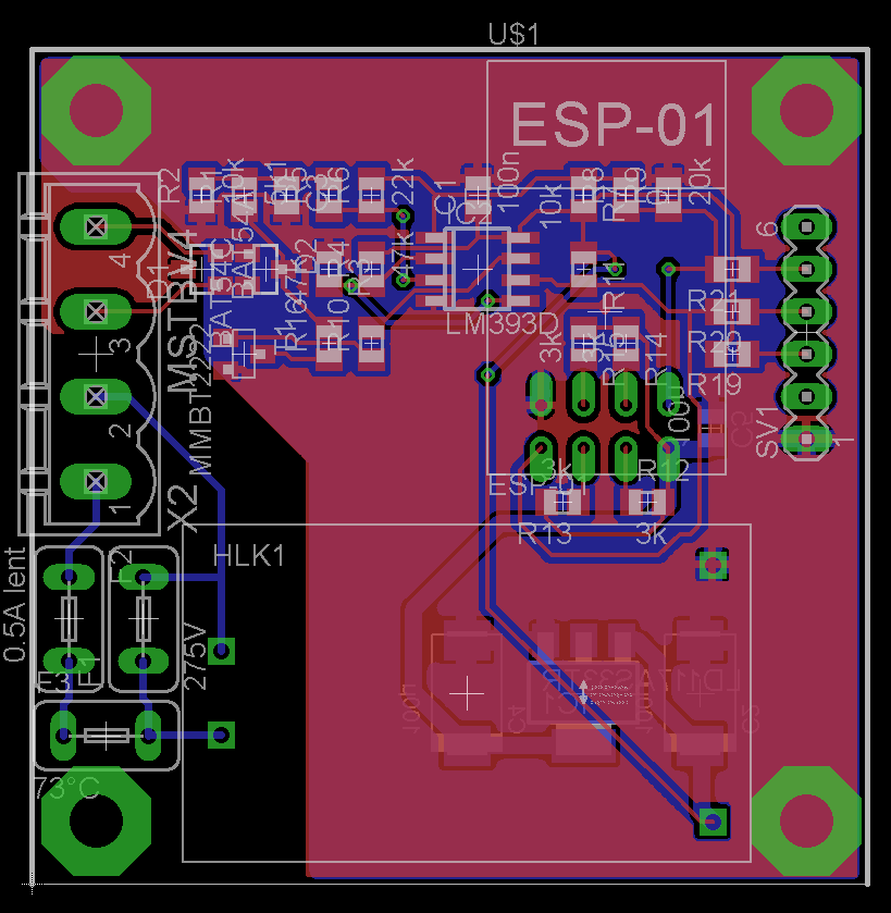
I limited the PCB size to 5cm x 5cm top save on the price on iTeadStudio:

- PCB.PNG (86.37 KiB) Viewed 718 times
The installation is fairly simple: just connect the system in parallel to the controller mains and connect the 2 VBUS wires with a twisted pair.
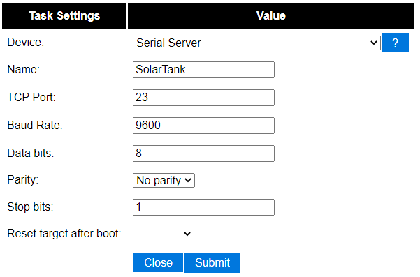
Then you need to flash the ESP8266 with the ESPEasy firmware and declare a "Serial Server" in the device list:

- esp.png (10.78 KiB) Viewed 718 times
This way, the ESP is acting as a Serial to TCP/IP bridge. Everything it receives on its RXD pin will be forwarded on the configured TCP socket.
Same in the opposite way, except that I never used the TX part (R11, IC2B, R10, T1, R16). I left these parts unmounted.
The remaining is at software level on the Raspberry Pi !
You can try checking for received bytes:
Code: Select all
sudo apt-get install socat
socat pty,link=/dev/ttyVBUS,raw tcp:192.168.0.103:23&
Now you have a /dev/ttyVBUS virtual tty device on which you should be able to receive the bytes from the VBUS controller:
Code: Select all
sudo cat /dev/ttyVBUS |hexdump

0000000 00aa 1200 2042 0500 0000 0000 0000 0600
0000010 10aa 1200 1042 0100 0307 0025 0126 3201
0000020 2238 2238 4605 0000 0200 7d00 036f 0000
0000030 0d00 0000 0000 7f00 0000 0000 7f00 0003
0000040 0000 7c00 00aa 1200 2042 0500 0000 0000
0000050 0000 0600 10aa 1200 1042 0100 0307 0025
0000060 0126 3201 2238 2238 4605 0000 0200 7d00
0000070 036f 0000 0d00 0000 0000 7f00 0000 0000
0000080 00aa 1200 2042 0500 0000 0000 0000 0600
0000090 10aa 1200 1042 0100 0307 0025 0126 3201
00000a0 2238 2238 4605 0000 0200 7d00 036f 0000
00000b0 0d00 0000 0000 7f00 0000 0000 7f00 0003
00000c0 0000 7c00 00aa 1200 2042 0500 0000 0000
00000d0 0000 0600 10aa 1200 1042 0100 0307 0025
00000e0 0126 3201 2238 2238 4605 0000 0200 7d00
00000f0 036f 0000 0d00 0000 0000 7f00 0000 0000
Now you need to compile and use the parser listed in the previous post:
Code: Select all
mkdir VBUS

cd VBUS

wget https://storage.googleapis.com/google-code-archive-source/v2/code.google.com/vbusdecode/source-archive.zip

unzip source-archive.zip

cd vbusdecode/trunk

g++ vbusdecode.cpp -o vbusdecode

~/VBUS/vbusdecode/trunk $ ll
total 36
-rw-r--r-- 1 eric eric   340 Feb 13  2016 raw.log
-rwxr-xr-x 1 eric eric 18980 Oct 25 14:29 vbusdecode
-rw-r--r-- 1 eric eric  9301 Feb 13  2016 vbusdecode.cpp
Example of parser usage:
Code: Select all
sudo cat raw.log | ./vbusdecode -c 1 0,15,0.1 2,15,0.1 4,15,0.1 6,15,0.1 8,7,1 9,7,1 10,7,11 11,7,1 12,16,1 14,16,1 16,16,1 18,18,1000 20,16,1000000 22,16,1,t
or
Code: Select all
sudo cat /dev/ttyVBUS | ./vbusdecode -c 1 0,15,0.1 2,15,0.1 4,15,0.1 6,15,0.1 8,7,1 9,7,1 10,7,11 11,7,1 12,16,1 14,16,1 16,16,1 18,18,1000 20,16,1000000 22,16,1,t
Depending on the options passed, you should get an output like this one:
Code: Select all
13.4 39.7 888.8 888.8 0 0 0 2 906 0 0 0 0 00:00
More information and all command line options can be found in the header of vbusdecode.cpp.
Now, let's make this automatic and connected to Domoticz !
First, I created a bash script to manage the socat automatically:
Code: Select all
eric@rpi1:~/VBUS/vbusdecode/trunk $ nano vbus.sh
#!/bin/bash

# Create socat redirection
(socat pty,link=/dev/ttyVBUS,raw,ignoreeof tcp:192.168.0.103:23,keepalive,ignoreeof) &

# Read from the SolarTank and return the decode frame
sudo cat /dev/ttyVBUS | ./vbusdecode -c 1 0,15,0.1 2,15,0.1 4,15,0.1 6,15,0.1 8,7,1 9,7,1 10,7,11 11,7,1 12,16,1 14,16,1 16,16,1 18,18,1000 20,16,1000000 22,16,1,t

# Kill remaining socat process
sudo pkill -f "ttyVBUS"
This script is then called by another Python script:
Code: Select all
eric@rpi1:~/VBUS/vbusdecode/trunk $ nano vbus.py
#! /usr/bin/env python
import os
import subprocess
# Domoticz description
domoticz_ip = '192.168.0.2'
domoticz_port = '81'
# Devices description
idx_panels = 204
idx_tank = 205
idx_pump = 206
# Output description
index_panelsTemp = 0
index_tankTemp = 1
index_pumpSpeed = 4
# Retrieve data
proc = subprocess.Popen(["./vbus.sh"], stdout=subprocess.PIPE)
(out, err) = proc.communicate()
# Display output
print 'Program output:', out
out = out.split()
# Display useful data
print 'Panels temperature: ', out[index_panelsTemp]
print 'Tank temperature: ', out[index_tankTemp]
print 'Pump speed: ', out[index_pumpSpeed]
# Push data to domoticz
os.system('curl \"http://' + domoticz_ip + ':' + domoticz_port + '/json.htm?type=command¶m=udevice&idx=' + str(idx_panels) + '&nvalue=0&svalue=' + str(out[index_panelsTemp]) + '\"')
os.system('curl \"http://' + domoticz_ip + ':' + domoticz_port + '/json.htm?type=command¶m=udevice&idx=' + str(idx_tank) + '&nvalue=0&svalue=' + str(out[index_tankTemp]) + '\"')
delta = float(out[index_panelsTemp]) - float(out[index_tankTemp])
os.system('curl \"http://' + domoticz_ip + ':' + domoticz_port + '/json.htm?type=command¶m=udevice&idx=' + str(idx_pump) + '&nvalue=0&svalue=' + str(delta) + ';' + str(out[index_pumpSpeed]) + ';0' + '\"')
Then you need to create the devices in Domoticz:

- domo.PNG (19.61 KiB) Viewed 718 times
The Python script will push the Tank temperature into the "Tank" widget and the Panels temperature in the "Panels" widget.
The Temp-Humidity device "Pump" is used to display "Panels-Tank" delta temperature and the Pump duty-cyle as the humidity.
And the last thing to do is to add an entry in the root crontab to call the script periodically:
Code: Select all
eric@rpi1:~/VBUS/vbusdecode/trunk $ sudo crontab -e

* * * * * cd /home/eric/VBUS/vbusdecode/trunk/ && (./vbus.py > /tmp/log 2>&1)
In case of any issue you can find the output of the last call into /tmp/log.