Digitemp & PL2303 (1-wire over UART)
Posted: Wednesday 19 July 2017 11:10
Hi people,
I recently discovered Digitemp which is a utility to read 1-wire sensors over a UART interface. I really like this solution because this does not involve plugging wires on headers for external sensors and such. But instead have a nice USB plug with integrated UART (pl2303 in my case). So it would be easy to plug in/out this adapter whenever I need to.
Just like this:

So I went ahead and soldered the Vcc & GND to the DS18B20 but I got confused how to connect the RX/TX to the 1-wire sensor.
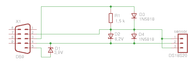
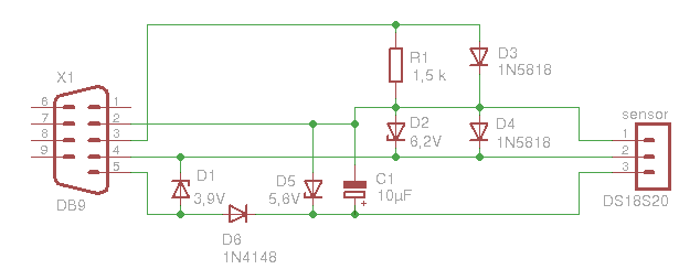
I saw these over complicated circuits:
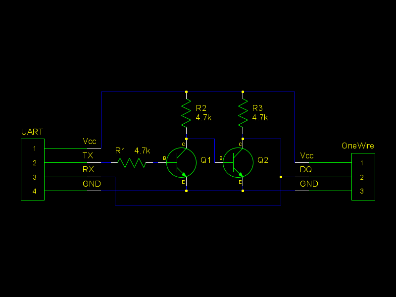
R1 = current limiting
R2 & R3 = Pull-up
Q1 & Q2 = Acting as the TX line of the 1-wire sensor
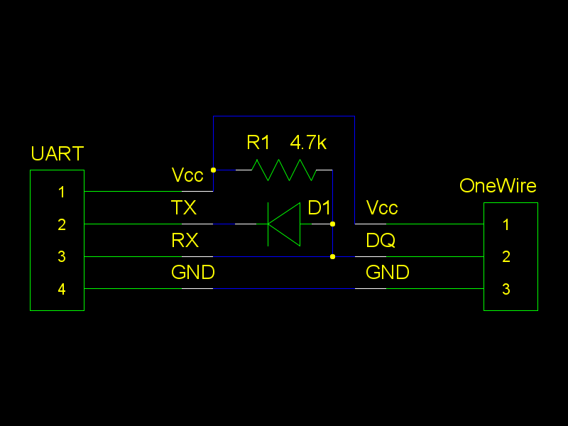
R1 = Pull-up
D1 = Unknown? Seems to block the TX of the UART interface
Ok I have to admit they are not that complicated, but still to much for this simple scenario. I thought since I can just short the Tx&Rx of a UART interface without any harm it should also be ok if I leave those Resistors/Diode/Transistors out. And my PL2303 already contained pull-up resistors on the PCB. So I went ahead and did just that. And what do you think? It worked perfectly without them! So I made a LUA script that runs the Digitemp binary for each attached sensor and updates a virtual sensor. This has been running for 4 sensors for about a week now without any hiccups.
I also tried this approach by leaving the Rx(white wire) unconnected, but this did not work for me.
So my final question, does anyone know what the purpose of adding those diodes/transistors is and if they can be left out without doing any harm?
Regards,
Timeless
I recently discovered Digitemp which is a utility to read 1-wire sensors over a UART interface. I really like this solution because this does not involve plugging wires on headers for external sensors and such. But instead have a nice USB plug with integrated UART (pl2303 in my case). So it would be easy to plug in/out this adapter whenever I need to.
Just like this:
So I went ahead and soldered the Vcc & GND to the DS18B20 but I got confused how to connect the RX/TX to the 1-wire sensor.
I saw these over complicated circuits:
R1 = current limiting
R2 & R3 = Pull-up
Q1 & Q2 = Acting as the TX line of the 1-wire sensor
R1 = Pull-up
D1 = Unknown? Seems to block the TX of the UART interface
Ok I have to admit they are not that complicated, but still to much for this simple scenario. I thought since I can just short the Tx&Rx of a UART interface without any harm it should also be ok if I leave those Resistors/Diode/Transistors out. And my PL2303 already contained pull-up resistors on the PCB. So I went ahead and did just that. And what do you think? It worked perfectly without them! So I made a LUA script that runs the Digitemp binary for each attached sensor and updates a virtual sensor. This has been running for 4 sensors for about a week now without any hiccups.
I also tried this approach by leaving the Rx(white wire) unconnected, but this did not work for me.
So my final question, does anyone know what the purpose of adding those diodes/transistors is and if they can be left out without doing any harm?
Regards,
Timeless