OK, so I managed to get a shift-register working.
A short explanation: A shift-register can hold up to 8 bits of information, which would be equal to 8 output pins on a Raspberry Pi or an Arduino.
You can combine several shift-registers to hold 16 bits, 24 bits, 32 bits and so on, of information. This is much more than the number of physical pins on a Raspberry Pi. For the transfer of data to the shift-register, you only need 3 pins, independent of the number of bits you will use.
A shift-register has a data-in-pin where the new bit-status is offered and a clock-pin that - when high - imports that data-bit. This is repeated for all 8, 16, 24 etc bits. When all bits are read, the latch-pin must be set high. At that moment the imported bits are copied to the output-pins.
The clock-timing should be about 1 milli-second. Well, this is the part I have not yet solved. If I set switches in Domoticz on and off without delay this goes far to fast for the shift register to process. And the only delay I know of in Domoticz is the 'AFTER 1' seconds option. This is of course way to slow, but... it is nice to follow the process happen.
If you build the following prototype, you can exactly follow what happens.
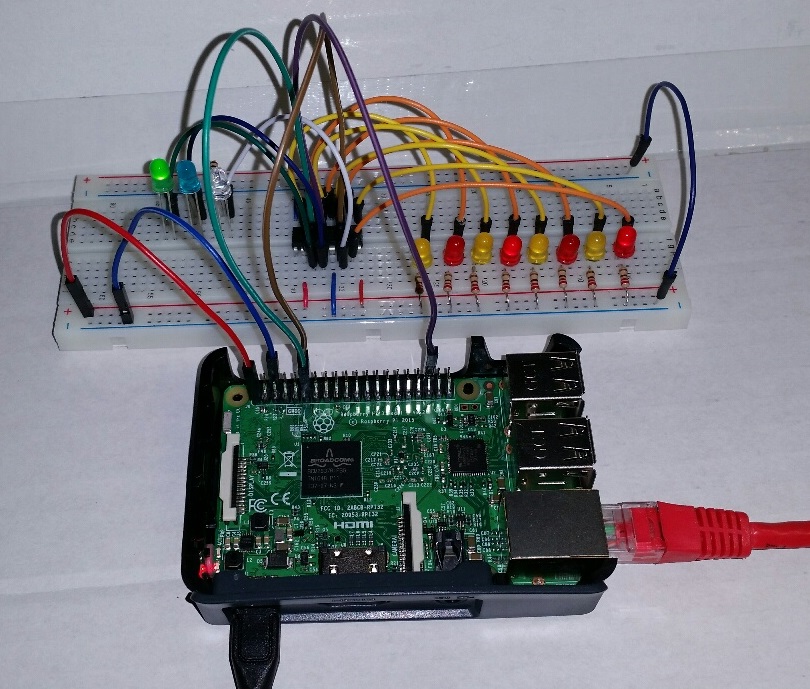
- RaspberryPiWithShiftRegister.jpg (208.55 KiB) Viewed 17443 times
And from the back:
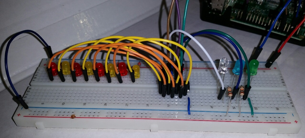
- Backside.jpg (233.31 KiB) Viewed 17443 times
The connection of the pins is explained in the script.
Code: Select all
-- GpioTest

commandArray = {}

  -- Make three gpio-switches in Domoticz.
  -- I choose names that tell where the switch is related to.

  -- In this script I use variables that indicate the purpose of the switches:
  local Latch = 'gpio16 (pin36)'
  local Clock = 'gpio17 (pin11)'
  local DataIn = 'gpio18 (pin12)'

  -- Pins on the 74x595 shift register
  --                __ __
  -- pin 1, Out 2  |  U  |  pin 16, Vcc
  -- pin 2, Out 3  |     |  pin 15, Out 1
  -- pin 3, Out 4  |     |  pin 14, Data in
  -- pin 4, Out 5  |     |  pin 13, Gnd
  -- pin 5, Out 6  |     |  pin 12, Latch
  -- pin 6, Out 7  |     |  pin 11, Clock
  -- pin 7, Out 8  |     |  pin 10, Vcc
  -- pin 8, Gnd    |_____|  pin 9,  Data out

  -- 'My' colors for the test
  -- Latch; on the 74x595, pin 12 = purple
  -- Clock; on the 74x595, pin 11 = green
  -- DataIn; on the 74x595, pin 14 = brown

  -- Connect pins 16 and 10 to power/plus/Vcc
  -- Connect pins 8 and 13 to ground/minus

  -- The shift register is powered by 3,3 volt.
  -- Otherwise the output-signals of the Raspberry Pi Pins (also 3,3 volt)
  -- would not be recognized as high.

  -- If you use two (or more) shift-registers, connect pin 9
  -- to pin 14 of the next chip.
  -- Also connect pin 12 to pin 12 and pin 11 to pin 11.

  print ("GpioTest started")

  local CmdCount = 0

  function SetLow(DeviceName)
    -- This function turns OFF the specified switch
    -- and so the related gpio-pin.
    CmdCount = CmdCount + 1
    table.insert(commandArray, {[DeviceName] = 'Off AFTER ' .. tostring(CmdCount)})
  end

  function SetHigh(DeviceName)
    -- This function turns ON the specified switch
    -- and so the related gpio-pin.
    CmdCount = CmdCount + 1
    table.insert(commandArray, {[DeviceName] = 'On AFTER ' .. tostring(CmdCount)})
  end

  -- These functions use the 'AFTER x' seconds delay.
  -- This means that each bit-state-change takes one full second.
  -- The shift-in of one data-bit needs four bit-state-changes and therefore 4 seconds.
  -- Of course this is way to long, it should be 1 milli-second.

  -- For now this is a proof-of-concept that nicely shows how the
  -- shift-register works.

  SetLow(Latch) -- Freeses the current state of the shift-register

  function ShiftOut(DataArray)
    SetLow(Clock) -- start clean
    SetLow(DataIn) -- no data yet
    SetLow(Latch) -- Close the Latch, this freeses the previous data
    for i = 8,1,-1 do
      -- the last bit is processed first, so it can shift to the end
      SetLow(Clock) -- prepare for receiving a new bit
      if (DataArray[i] == 0) then
        SetLow(DataIn) -- when the bit is low, set the input low
      else
        -- when the bit is low, set the input low
        SetHigh(DataIn) -- when the bit is high, set the input high
      end
      SetHigh(Clock) -- this changes makes the shift-register read the data-bit
      SetLow(DataIn) -- reset the data-bit
    end -- repeat for all 8 bits
    SetLow(Clock) -- finishes the last read
    SetHigh(Latch) -- Open the latch, this makes the input available on the output pins
  end

  ShiftOut({1,0,0,1,1,1,0,1})

  print ("GpioTest ended")

return commandArray
You can see what the script is sending by the green, blue and white leds:
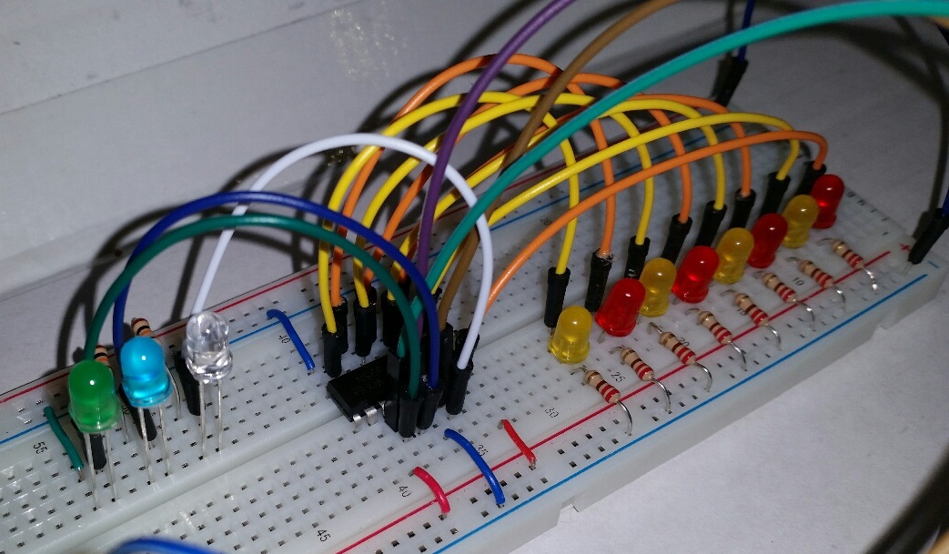
- Leds4.jpg (212.03 KiB) Viewed 17443 times
When the blue led is off, the shift register is ready to receive information.
When the white led is on there is a bit with the ON state presented. When the white led is OFF, there is a bit with the OFF state presented.
When the green led turns ON, the state as indicated by the white led is read and processed by the shift-register.
This is repeated 8 times.
After that you will see the blue led turn on. At that moment, the input-bits are copied to the output-pins of the shift register.
Well, my next challenge is to find a way to set Domoticz switches with an interval of 1 milli-second.
If you would be the one that knows how to achieve this... please tell me.