The Software
A program for an Arduino is called a Sketch. I am not at all an Arduino specialist but I googled until I had the working parts for my program, uh... sketch.
For the communication I use two libraries that allow to send KaKu commands. These libraries are NewRemoteReceiver and
NewRemoteTransmitter. You can find them and install them on the internet. That goes beyond the scope of this article.
The sketch initializes the Arduino by telling what connectors (pins) have what purpose. Also, the device-addresses are defined. You can decide if you will use debugging and if you want to use the return-channel.
When the sketch starts, the device-addresses are translated to numerical values. All relays will be off. So the sketch sends an off-command to Domoticz so that the states are equal. Also the return-channels are reset.
The Sketch should be self-explainatory.
Code: Select all
#include <NewRemoteReceiver.h>
#include <NewRemoteTransmitter.h>

#define MonitorLed 13

bool Debug = true;
bool UseReturnChannel = true;

String KaKuCodeInHex = "1A0EEEE"; // address of switches to turn on or off
String KaKuCodeOutHex = "1A0EEFE"; // address of the return channel devices

unsigned long KaKuCodeInNum = 0; // will contain the numerical value
unsigned long KaKuCodeOutNum = 0;

int RelayPin[4] = {8, 9, 10, 11}; // each relay has its own pin
int RelayState[4] = {0, 0, 0, 0}; // all relays begin Off
int ResponsePending[4] = {0, 0, 0, 0}; // No reponses pending yet
int SelectUnit = 0; // will contain the number of the selected unit

unsigned long LastCommandTimer = 0;

// Function KaKuHexToNum translates the hex-address of a device
// to the numerical equivalent.
unsigned long KaKuHexToNum(String HexInput) {
  String HexChars = "0123456789ABCDEF";
  unsigned long result = 0;
  for (int i = 0; i<7; i++) {
    result = result * 16 + HexChars.indexOf(HexInput.substring(i, i+1));
  }
  return result;
} // KaKuHexToNum

// Function KaKuSend transmits the confirmation of a received
// command.
void KaKuSend(unsigned long SendAddress, int SendUnit, bool SendState) {
  if (Debug == true) {
    Serial.print("Zenden: ");
    Serial.print(SendAddress);
    Serial.print("; Unit: ");
    Serial.print(SendUnit);
    Serial.print("; State: ");
    Serial.print( SendState);
    Serial.println("");
  } // if Debug
  // When sending commands, the receiver should be disabled.
  // Otherwise the Arduino will flood itself.
  NewRemoteReceiver::disable();
  NewRemoteTransmitter transmitter(SendAddress, 3, 260, 3);
  // address, pin, duration, repeat-factor (2^3)
  transmitter.sendUnit(SendUnit, SendState);
  // and re-enable the receiver again.
  NewRemoteReceiver::enable();
} // KaKuSend

void setup() {

  // Calculate the numerical equivalents of the device-addresses.
  KaKuCodeInNum = KaKuHexToNum(KaKuCodeInHex);
  KaKuCodeOutNum = KaKuHexToNum(KaKuCodeOutHex);

  if (Debug == true) {
    Serial.begin(115200);
    Serial.print("Listen to: ");
    Serial.print(KaKuCodeInNum);
    Serial.println("");
  } // if Debug

  // Initialize receiver on interrupt 0 (= digital pin 2), calls the callback "ProcessCode"
  // after 2 identical codes have been received in a row. (thus, keep the button pressed
  // for a moment)
  NewRemoteReceiver::init(0, 2, ProcessCode);
  // See the interrupt-parameter of attachInterrupt for possible values (and pins)
  // to connect the receiver.

  // Initialise the Arduino data pins for OUTPUT
  Serial.println("Initialize...");
  for (int i = 0; i<4; i++) {
    pinMode(RelayPin[i], OUTPUT); // select pin for this relay
    digitalWrite(RelayPin[i], LOW); // switch relay off
  }
  pinMode(MonitorLed, OUTPUT);

  // Blink the led on the Arduino three times to show the Sketch has started.
  if (Debug == true) {
    for (int i = 0; i<3; i++) {
      digitalWrite(MonitorLed, HIGH);
      delay(300);
      digitalWrite(MonitorLed, LOW);
      delay(300);
    } // for i
  } // if Debug

  Serial.println("Reset Switch-states...");

  // Reset the states of the switches in Domoticz.
  for (int i = 0; i<4; i++) {
    KaKuSend(KaKuCodeInNum, i, false);
    delay(100);
  }

  // Reset the states of the return-channels in Domoticz.
  if (UseReturnChannel == true) {
    Serial.println("Reset Return-channels...");
    for (int i = 0; i<4; i++) {
      KaKuSend(KaKuCodeOutNum, i, false);
      delay(100);
    }
  } // if UseReturnChannel

  // Blink the led on the Arduino three times to show the Sketch has initialized.
  if (Debug == true) {
    for (int i = 0; i<3; i++) {
      digitalWrite(MonitorLed, HIGH);
      delay(300);
      digitalWrite(MonitorLed, LOW);
      delay(300);
    } // for i
  } // if Debug

} // setup

void loop() {

  if (UseReturnChannel == true) {

    // wait for 2 seconds no 433 Mhz Traffic
    if ((millis() - LastCommandTimer) > 2000) {

      if (Debug == true) {
        Serial.print(LastCommandTimer);
        Serial.println("");
      }

      for (int i = 0; i<4; i++) {
        if (ResponsePending[i] > 0) {
          KaKuSend(KaKuCodeOutNum, i, RelayState[i]);
          ResponsePending[i] = ResponsePending[i] - 1;
          break;
        }
      } // for all relays

      LastCommandTimer = millis();

    } // 1 second no traffic

    delay(100);

  } // if UseReturnChannel

} // Loop

// ProcessCode function is called when a valid KaKu-code is received.
void ProcessCode(NewRemoteCode receivedCode) {

  // Save the counter for the last command
  LastCommandTimer = millis();

  if (Debug == true) {
    Serial.print("Received: ");
    Serial.print(receivedCode.address);
    Serial.print("; Unit: ");
    Serial.print(receivedCode.unit);
    Serial.print("; Type: ");
    Serial.print(receivedCode.switchType);
    Serial.println("");
  } // if Debug

  // The four devices are numbered from 1 to 4 in Domoticz.
  // The transmitted unit-numbers count from 0 to 3.
  SelectUnit = receivedCode.unit;
  if (SelectUnit > 3) {
    return; // Can't be for the 4RelaySwitch
  }

  // KaKu commands can contain On, Off or a Dim command.
  // The Dim command is not used in this Sketch. We treat it as an On command.
  switch (receivedCode.switchType) {
    case 0:
      RelayState[SelectUnit] = LOW;
      break;
    case 1:
      RelayState[SelectUnit] = HIGH;
      break;
    case 2:
      RelayState[SelectUnit] = HIGH;
      break;
  } // switch switchType

  // Now, see if the received code contains the address of the 4 Relay switch.
  if (receivedCode.address == KaKuCodeInNum) {
    // This program-part is only executed if the received address
    // was identical to the address of the 4 Relay switch.
    // Set the Relay accordingly
    digitalWrite(RelayPin[SelectUnit], RelayState[SelectUnit]);
    ResponsePending[SelectUnit] = 2; // 2 confirmations
  } // if KaKuCoddeInNum

} // ProcessCode
I suggest you develop the Sketch bit by bit. The use of relays and RF communication is widely described on the internet.
First see if you can switch the relays without the use of communication.
Then, make a different sketch and see if you can receive and interpret KaKu commands. The library NewRemoteReceiver has perfectly usable examples. The same goes for examples from the NewRemoteTransmitter library.
If you combined this to a working system, add the return-channel.
When it all works, disconnect the development-computer, connect the power from the USB power and close the housing.
Then, the system should work stand-alone.
After testing and verifying you can close the housing and you should have something like this.
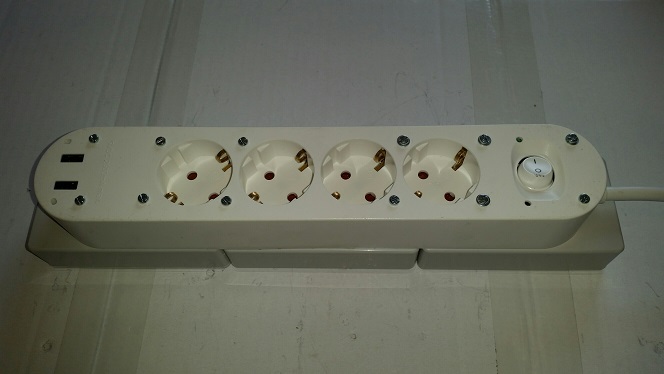
- 4RelaySwitchFinal.jpg (46.04 KiB) Viewed 2086 times